- Domů
- Povrchové úpravy
- Povrchové úpravy
- Brief Specialist Information
Brief Specialist Information
For the designer in mechanical engineering and precision mechanics, but also for the interested professional buyer, knowledge of the physical relations involved in galvanization is of great use.
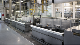
The figure 1 depicts the principal construction of a galvanic “tub” (or “bath”) for the deposition of metals such as copper, nickel, zinc and others. A simplified schematic of this highly complex process is described on the two following pages.
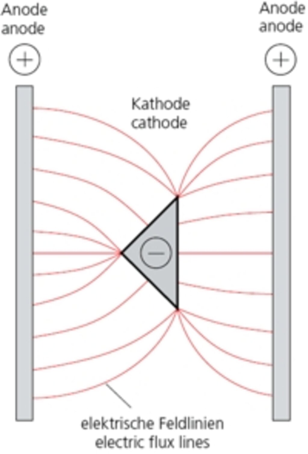
Abb. 2.1
Through the application of a direct current (of approx. 5-20 V), zinc atoms (ions) will migrate inside the bath from the positive pole to the negative pole, e.g. during zinc-plating in a saline solution. On the current-carrying bar of the positive pole in this example, zinc plates (anodes) are located, which are gradually used up. On the middle bar (negative pole) the items being zinced are suspended.
The metal ions (electroconductive atoms) migrate along from flux lines on to these items, whereby the metal coating also increases with the increase of the flux line thickness. Points and edges will tend to “attract” the flux lines (see figs. 2.1 and 2.2) – as in a magnetic field.
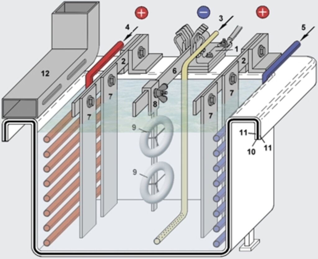
Abb. 1: Aufbau eines galvanischen Zinkbades
1. Kathodenanschluß
2. Anodenschiene aus Kupfer mit Anschlüssen
3. Luftzuführung zur Elektrolytumwälzung
4. Heizregister
5. Kühlregister
6. Warenschiene, motorisch bewegt in vertikaler oder horizontaler Richtung
7. angeschraubte Zinkanode
8. Werkstückträger
9. zu galvanisierendes Werkstück
10. Stahlbehälter (”Wanne“ oder ”Bad“)
11. chemikalienbeständige Gummierung
12. Luftabsaugkanal (an beiden Wannenrändern)

Abb. 2.2
Schichtaufbau bei einem Profil entsprechend Abb. 2.1

Abb. 3.1
galvanisch beschichtet

Abb. 3.2
lackiert
With rear areas the reverse will happen (see figs. 3.1 and 4), causing the metal deposition to stop altogether eventually, e.g. in pipes depending on the diameter and length (see fig. 5).
For the design engineer the knowledge of this physical effect is of great importance, especially at fits. Moreover, the fact, that gaps of assembled components are only coated in the rarest cases, is of equal interest. Here, the oozing out of corrosion products after a certain time is the normal case. The same applies to porous spots from welding and to corrosion holes (see fig. 6).
Depending on the deposited layer thickness, a levelling effect is also present (especially with gloss nickel), which levels out minor unevenness of the component surface.
Compared to varnishing, electrolytically (galvanic) deposited metal coatings differ considerably due to the aforementioned effect (see figs. 3.1 and 3.2).
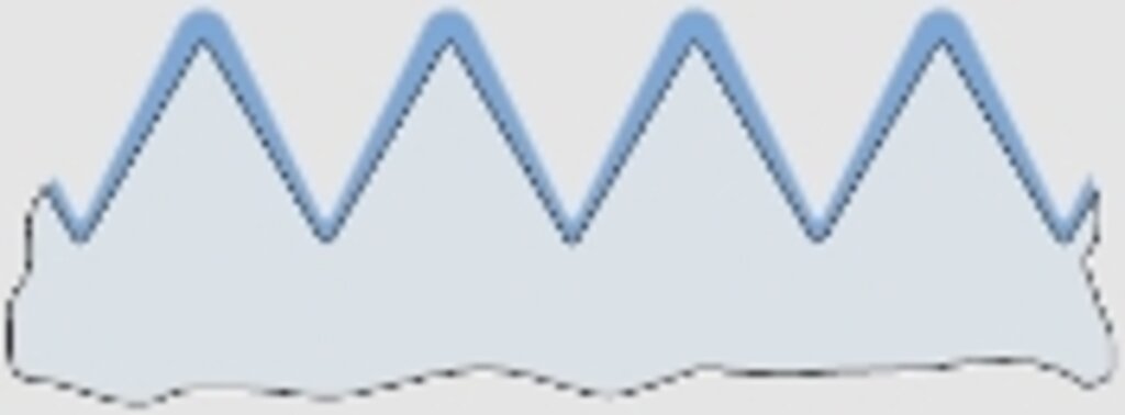
Abb. 4
Gewindequerschnitt
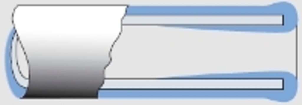
Abb. 5
Schichtdickenverlauf bei einem Rohr
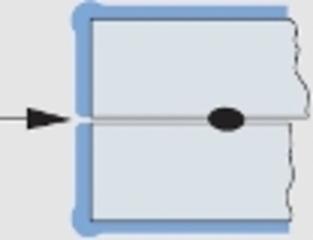
Abb. 6
Schichtaufbau bei zusammengesetzten Bauteilen.
Gefahr des Austritts von Korrosionsprodukten, da keine Beschichtung
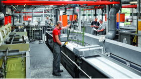
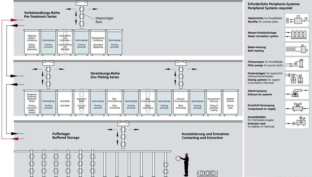
Setup of a Galvanic Automat
In order to present the entire electroplating workflow in a form comprehensible to the interested non-specialist, the rinsing processes have been presented in a simplified form and the traverse paths of the product displacers omitted. Peripheral systems as well as necessary additional areas are depicted in the block diagram.
The number of processing steps (immersion processes with different dwell times) constitutes, depending on the cleaning, approx. 20 – 26 units, e.g. for zinc-plating, at a normal processing time of around 2.5 hours. The nickel-chrome series also present in the galvanic automat is left out here. The setup of all galvanic systems is principally the same (even for anodizing); at manually operated systems, which are used for non-automated items or for small batches, the bath arrangement is merely adapted to the operator control.
Kontakt

Rohde AG
Industriestrasse 9
D - 37176 Nörten-Hardenberg
Telefon.: +49 (0) 5503 9860-0
Telefax: +49 (0) 5503 9860-11
info@rohde-technics.com


